“It is the ever-present fallibility of electronics that keeps the compass adjuster in business,” Capt. George Barber said when asked to explain the science and art of swinging a compass. Three years into his retirement, the 75-year-old mariner, teacher, compass adjuster and businessman displayed a half-dozen compasses — both assembled and in parts — to show how it all works.
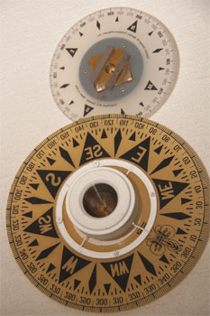
Barber started by providing a basic overview of the construction of a magnetic compass. The compass card, in the most common configuration, has an inverted cone under the center. This will typically have a jeweled fitting to receive the compass needle that is mounted on the base of the compass bowl. The U.S.-made Dirigo Compass that has a needle mounted on the card represents a variation of this. The needle turns in a cavity at the top of the little shaft coming up from the base of the bowl. In the center of the card, above this assembly, a bubbled section, which can be seen from above, contains a liquid that helps the card to float as lightly as possible in the fluid of the bowl. The fluid serves to dampen the motion of a marine compass when the vessel is at sea. Compasses built in Europe or Japan have a 50/50 mix of distilled water and alcohol, while those built in the U.S. have a light oil. A setscrew in the side of the compass bowl allows the fluid to be topped up.
 |
|
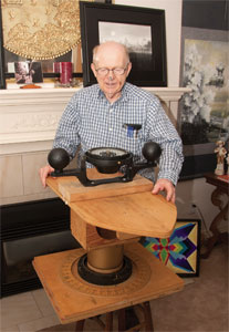
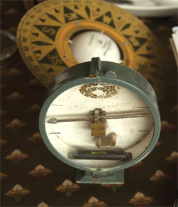
Capt. George Barber, 75, uses a training device to demonstrate the swinging of a compass. He has been a compass adjuster for 23 years. |
“When the compass is cold,” Barber explained, “its fluid shrinks, creating a suction force inside the compass that could cause a bubble if a compass bowl leak source was present. So once you have topped the cold compass up with fluid as need be (then re-fastened its filler plug setscrew), when the compass has rewarmed is a good time to check it again for leaks, this time with the fluid as newly pressurized.”
Most compasses have an accordion of flexible metal in the bottom, or a fluid-tight air chamber to allow for expansion and contraction of the fluid with temperature changes. If Barber goes aboard a vessel to swing the compass and finds that there is or has been a fluid leak, he could require the owner to replace the compass or have it factory-serviced as need be.
Assuming the compass appears to be in sufficiently good mechanical order, Barber will take his primary instrument out of his pocket. This is a typical little steel tape measure available in any building supply. “When the metal tape is coiled it will not influence the compass with much force,” he said, before pulling out a 10- to 12-inch length of the tape. With the ship stationary (before the ship departs would be a good time), he would slowly approach the mounted compass with the slightly extended tape, until the dial assembly was deflected two degrees only, in each rotational direction. After the magnetic deflector tape is removed following each deflection, where the compass settles is carefully observed. “For a compass to demonstrate absolute freedom from pivot-and-jewel friction, it must return consistently and completely from each two-degree rotational deflection. Otherwise the compass proves it can’t provide correct heading information, no matter what adjustment process is attempted.”
 |
|
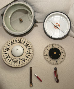
Two types of compass bowls with a valved glass bottom at left and accordion metal body at right, plus the corrective magnets. |
The first magnetic measurement, Barber noted, is of the vertical gradient at the compass position. “This is also usually best checked and resolved before the ship leaves her dock.” To measure this, Barber would remove the compass from its gimbals and place his vertical force instrument in its place. This device has a magnetic bar balanced in a round dial the size of an alarm clock with the magnet set parallel to the keel of the vessel. The magnet would register any downward pull and corrective vertical magnets could be placed under the compass.
Then, the actual swinging of the compass, or more accurately swinging the ship with the compass and correctors attached, is a relatively straightforward combination of precise measurement and a steady eye. Directing the vessel to an open area some distance from shore, Barber will have it stopped. He affixes a small plastic mount to the compass glass over the center of the compass rose. He then takes a very thin rod of about 18 inches from a protective case and fixes it to the plastic holder, creating a “center pin” for taking horizontal bearings. Stepping back from the compass he visually aligns the rod, first with the compass lubber’s line and the ship’s center mark forward, thus checking compass fore and aft alignment. The sight pin is used to determine a fixed distant vertical mark, on land as far away as visually possible. Eleven miles is considered a good distance, allowing a bigger turning circle, although a nearby building’s vertical edge could be used.
More than one distant mark may be needed depending on visual interference from other marine traffic, weather or shadow effects from shipboard items. Having noted the line(s) of position of the distant mark(s), he will direct that the ship be swung. This can be done by tugs or by its own thrusters so that the ship revolves in its own length. As the shipboard compass is probably mounted topside, he can then keep his “principal eye” — the eye that is most comfortable to use for measuring distant bearing(s) on shore via the sight pin mounted on the compass. As the ship rotates, the compass card remains mainly fixed on north; so by being able to measure and record the relative bearings every 10 degrees, Barber will note any deviation, which he removes by adjusting hard-iron correctors for Coefficient B and C (horizontal fore and aft and athwartship magnets); soft-iron Coefficient D (soft iron spheres acting inter-cardinally from effects of continuous shipboard side-to-side soft iron); and vertical soft iron (Flinders bar) acting fore and aft as the soft iron component of Coefficient B, keeping the compass happier on E/W courses with change of latitude. “The compass card is getting its very life energy from magnetic forces which this process of compass adjustment releases and maximizes,” he said.
 |
|
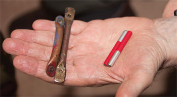
Corrective magnets, colored red and silver to indicate north and south poles, are placed inside non-magnetic copper tubes. |
If there is any inconsistency of the compass as this rotation takes place, it is noted as variable deviation of the compass, likely caused by electromagnetism or reaction to turning of shipboard metal. If it is some local and temporary magnetic distraction (called a magnetic anomaly) he will direct corrective action.
The compass adjuster knows that compass inconsistency can be affected by moving the metal balls mounted to port and starboard as noted above. “But two balls outermost can provide too much inter-cardinal correction, a fairly common experience. Thus, one ball can be removed and the fine-tuning of Coefficient D deviations engineered with the remaining ball, most often ever-so-slightly adjusted toward center,” Barber said.
 |
|
The underside of two compass cards showing the cone-shaped hole that rests on the pin to minimize friction. |
While the deviation of a compass obviously has a measured and scientific definition, there is a skill component identifying and correcting a deviation that approaches an art. “With time you can see a deviation as slight as half a degree,” Barber said, “so I can usually correct any deviation with two complete rotations of the vessel. Although with greater problems it may take three turns.” Among the magnetic anomalies are weird disturbing fields from direct hits of lightning to the vessel, which ultimately decay with time and normal vessel vibrations.
Over his 23 years in the business, Vancouver-based Barber traveled regularly to adjust compasses for cruise ships in Mexico and for Alaska State Ferries. He has been flown to meet ships in Panama and other ports for urgent jobs. Having apprenticed in Nova Scotia under Capt. Andrew J. Rae, whose son George Rae is now in the profession, Barber often traveled to the East Coast and Great Lakes to adjust compasses. For each new location he would have to ascertain the natural deviation of true north from magnetic north. This varies both geographically and over time. In the past 23 years, the natural deviation for Vancouver Harbour, currently “less than 20 degrees East,” has decreased.
 |
|
The vertical force instrument is put in place of the compass once it has been removed from the gimbals. This measures magnetic anomalies in the vessel. |
As an independent compass adjuster, Barber ran a little ad in most Canadian marine publications. His name was synonymous with compass in British Columbia and abroad. He explained that calls for his services were prompted by three general reasons: a poorly performing compass-dependent autopilot, regulatory requirements under national government or the International Maritime Organization, or simply because the captain wanted his compass to function with more precision.
Most autopilots, such as the Wagner, function by placing a coil (compass sensor) under the compass that converts the directional pull of the magnetic compass to electrical impulses that are transmitted as course adjustment signals to the autopilot. If the compass is wandering this will tend to make the boat wander on its intended course.
Barber is dismissive of those who would rely on gyro or GPS compasses, especially the complex and expensive gyrocompass. He stresses that anything that is dependent on electricity for its operation is inherently unreliable. The earth’s magnetic fields have been assisting mariners since the times of the ancient Chinese navigators right up to those on modern vessels. The array of electronic navigation aids found on most contemporary vessels has not driven the compass from its well-deserved central position on the bridge.